Building Odyssey

Welding Tests and Prep Work
Sunday, June 21, 2009
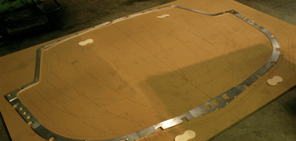
Each transverse frame consists of up to eleven separate cut parts which must be welded together in a super-precise manner. The MDf loft floor has the outer profile lines incised into it to serve as a guide in oriented the parts. Originally I had envisioned simply placing the parts in the correct positions, screwing some step clamps to the MDF to hold them in place and welding. The reality is a bit more complex. The frames have a set of 2” holes for wiring and plumbing installation, as well as larger holes in the floors to allow for some pipes as well as connections between tankage sections. Alumar advised me, and I agreed , to reinforce the holes with short sections of pipe welding into the holes 100%. The frames are 3/8” ( 10mm) thick, so I figured double the thickness on either side ( 3/4”, 20mm), plus the thickness of the frames for 2-7/8” ( 60mm). Because welding distortion is a fact of life in metalworking a decision had to be made as to whether to weld the pipe sections in before or after assembling the frames. Before seemed to be a better choice as it allows smaller pieces to be manipulated quickly, turned frequently to balance the welding forces, and then, if there is any distortion to more easily correct it. A test using 3” wide, rather than 4”, 6061 showed that is is possible to weld in the pipe sections with no distortion, but only if the parts are small. Trying to quickly rotate a 13’ wide frame would be tough.
Having the pipe sections welded into the frames means that the other frame sections will have to lifted off of the loft floor by an amount equal to the pipe projection, 3/4” ( 20mm). 5” lengths of cold rolled steel with nice clean edges were cut to raise the frames. It will make aligning to the incised lines slightly more difficult.
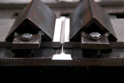
The other welding distortion issue is the flat butt weld of each frame section to the next. I did multiple tests trying to dial in the welding parameters and design the best joint configuration to obtain 100% fusion and limit the distortion. I fabricated a plate clamp which holds the 2 sections in alignment and also perfectly flat and raises the sections the required 3/4”. The amazing result was that I can make a full continuous weld on 1 side , let it cool, and the 2 pieces are absolutely straight. Then I back-chip the weld to remove the underside contamination and weld side 2, also held in the clamp.
After some more pondering and testing, I decided it would be useful to weld up several subassemblies of 2 or 3 sections of frame, rather than trying to weld everything at once. That may if any errors arise, they are more easily dealt with in the smaller units. I have learned in my blacksmithing, and my sailing, that the key to maintaining a straight course is constant minor correction. So, on Sunday, June 21, I actually started welding the boat together, joining 2 sections, port and starboard, on Frame I ( eye)
Actual work!


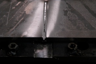
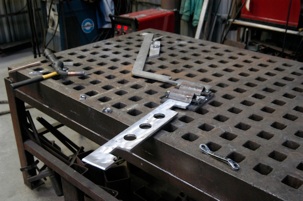

10mm plate beveled at 45˚ to a depth of 4mm
Back-chipping using a variable speed grinder on lowest setting and a 36 T carbide blade. It’s been called the Meat Axe, and I can see why. Total present-moment thinking is required with this tool. It makes quick work of the job and does not introduce contaminates into the weld zone like and al. ox. disc would.
The Lincoln Power Mig 300 is a synergistic type welder which automatically adjust several parameters jointly. Which leaves the other 8 for me to figure out, as well as arc length and travel speed. After many tests I made good progress in understanding how one factor affects the others. After I made what I thought was a good weld I placed the sample in a post vise and beat it with a big hammer-very relaxing.
I have spent many, many hours welding all types of metals over the past 30 years: steel, stainless, silicon bronze, aluminum bronze, copper and aluminum. The welding I’m learning to do now is by far the most technical, and the most satisfying, because I know that it is right. My new bedtime reading is “The Practical Refernce Guide for Welding Aluminum” by American Welding Society. The cover picture is of the LEM, on the Moon, with an astronaut saluting the flag.This is the manual given to the blokes who weld on spacecraft, so if it’s good enough for them...it ought to work for me
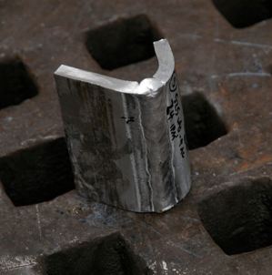
The first weld on Odyssey.


