Building Odyssey

Rudder Bearings
Friday, December 10, 2010
The Jefa rudder bearings are the first manufactured component to be installed on the boat. Made in Denmark, the bearings consist of a 115mm diameter double roller assembly housed in a spherical nylon swivel, all set in a very stout turned aluminum housing. The swivel allows up to 8˚ of rudder shaft misalignment, which makes installation easier and, more important , allows the bearing to turn if the shaft gets slightly bent in a collision or grounding. The thought of the 4-1/2” (115mm) 6082 alloy shaft being bent is hard to imagine, but, with a 34,000 lb displacement, huge forces could be generated. The 6082, by the way, has higher tensile and shear numbers than 5086, nearly as high as 6061, but with better corrosion resistance. Aluminum of this type is actually superior to stainless, of equivalent weight, due to it’s more elastic nature. And stainless wouldn’t work anyway in this type of rudder blade fabrication due to galvanic issues.
The 85mm upper bearing is housed in a flanged aluminum housing with a screw-on deck plate cover. I had the shaft turned at a local machine shop that does frequent aircraft work. Their tolerances were amazing, -0.00mm/ +.05mm, and the shaft looks beautiful, replete with a 35mm square hole in the top end for the emergency tiller.
Installing the first “component”.
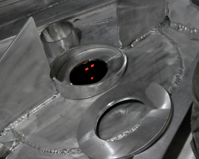
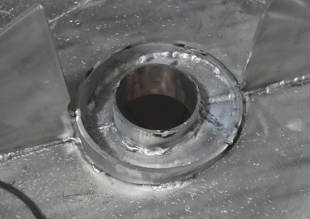
The parts of the rudder bearing leveling platform include and angled outer collar, a 10mm top plate and a 6mm inner sealing tube. The red LED’s of the welder can be seen through the rudder port. Also, note the large 10mm insert plate in the hull bottom. The 2 angle braces on the right and left are part of the centerline stringer.
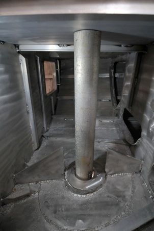
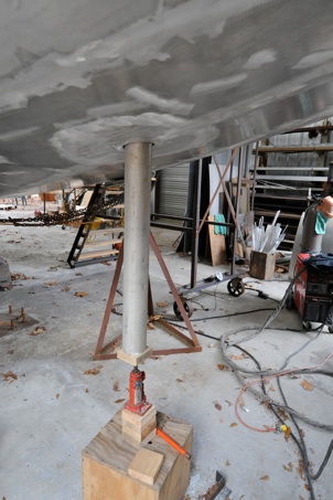
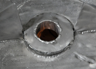
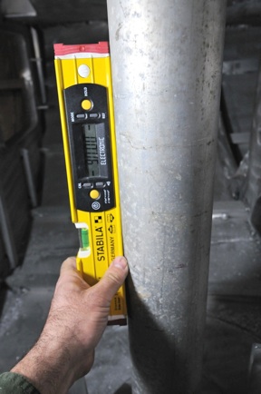
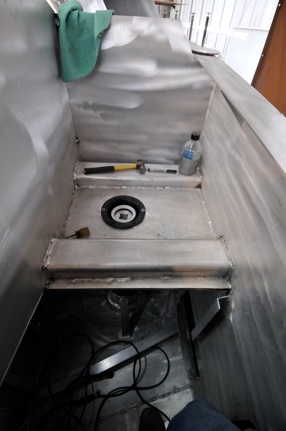
The inside welds were completed, making the platform waterproof inside, then the top plate was welded, and ground flush. Grinding in the lazarette is unpleasant, to say the least. Next , to determine the location of the upper bearing, I used a lightweight piece of 4-1/2” /114mm OD pipe , which is 1mm smaller than the rudder shaft, to project the shaft onto the underside of the cockpit sole. Again, having the entire boat hull level from side to side and fore/aft makes this technique possible. I cut the upper bearing hole with the plasma cutter using a hardboard template. This hole must be very close tolerance, as the flange screw holes are very close ( too close, actually) to the inner edge. Jefa should make the flange 6mm larger. I installed a 5mm doubler plate on the underside, then drilled the holes.

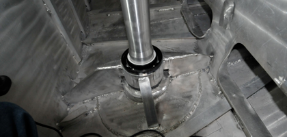
I then slipped the actual rudder shaft up through the lower bearing, again carefully centering it in the port and exactly plumb. Even though the bearings allow for some misalignment, it’s best to at least try to make it perfect. With the shaft wedged in place from below, the bearing housing was tacked in place to the leveling platform. Because the guts of the bearing are nylon, these had to be removed prior to fully welding, as they might melt. The bearing was then fully welded around its bottom perimeter. I rolled a sleeve from 5mm plate, and slipped it over the bearing (after removing the shaft) and welded this to the centerline stringer as well as two side braces made from 50mm Tee. That sucker ain’t goin’ nowhere.
From the shaft cut-off, I had the machinist turn and bore a collar that that will fit the 85mm upper part of the shaft. This I will split and use to install the tiller arms for the steering and windvane. But that’s another story...


