Building odyssey

Rigging The Hull For Turning
Tuesday, September 21, 2010
And , after 16 months and approximately 1200 hours ( I do try to keep up with the hours on a spreadsheet) I am ready to turn the hull. The plan is to use the “ roasting spit ” method. Dix has an article about various methods of turning a hull available through his website. The basic idea is to attach a pipe at a certain level to the stem and another to the transom, which then rest on a stout pivot point. Chain hoists or a crane or forklift are then used to control the rotational motion of the hull as it flips over. The appeal of this method to me is that the hull i never suspended from any straps or chains, rather the weight is borne by the pipe and pivots.
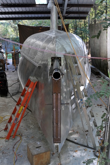
No, that’s not a battering ram.
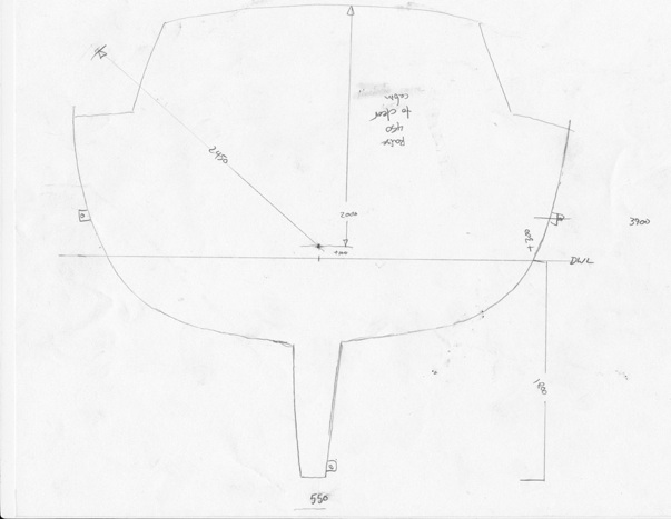
The diagram above a helped me to figure out what needed to happen: in order to clear the corners of the pilot house, the hull would need to be lifted up about 450mm, then set down -200mm from it’s original position to rest the keel on the ground. Robert at Alumar had suggested, based on some skin calculations , that the CG would be about 100-120mm above the DWL. This was also fairly close to the geometric center of the vertical axis, so seemed like a good place to start.
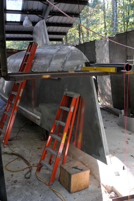
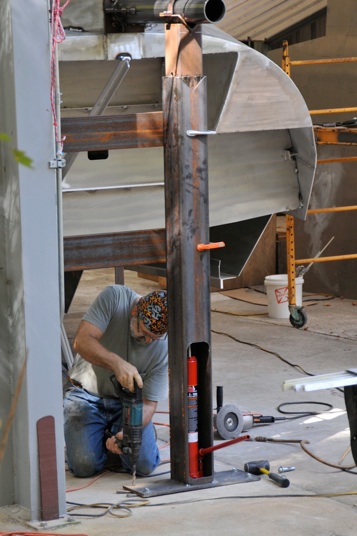
I designed a couple of hydraulic lifts for either end, using a 5” square steel tube sliding inside a 6” square tube, lifted by a 3 ton long-reach hand operated hydraulic jack. A section of angle iron is the pivot cradle.
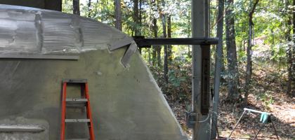
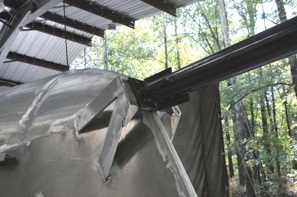
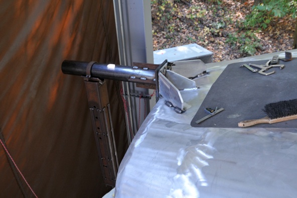
The axial pipe is 4” schedule 40 steel. The section on the stern is short, about 32” , but the bow pipe has a span of 44”, so I made sure to reinforce it well. The nice thing ( one of many) about aluminum is that the welds are strong, but can easily be cut and removed later, so when attaching the pipe to the boat I wasn’t constrained in making welds. I kept imagining the boat turned sideways and how the forces would be acting on the pivot pipe and joint. I also used a cool online deflection calculator at www.calculatoredge.com/civil%20engg%20calculator/beam.htm#. I’m definitely not an engineer, but have a practical understanding of physics and mechanics, and a working knowledge of the strengths and weakness of materials, so I get by. However, this is the first 5500 pound boat hull I’ve ever turned...and I don’t want to drop it.
When thinking about where the axis should be located, we talk in terms of relative to the DWL, datum ( or design ) water line. The Alumar kit has small holes milled into the frames at the DWL, one of the beauties of CNC. But these points are on the inside of the hull. How to transfer them to the outside when the concrete floor below is very uneven, by many inches in some areas? I first used a convoluted method involving levels and plumb lines and tape measures, and placed some points. But I didn’t feel totally comfortable with them. Then it dawned on me that I had the perfect flat level surface of a known 1800mm distance form the DWL: the bottom of the keel.Using the rotating laser level it was simple to setup and transfer points around the hull from above, all
referenced to the same plane. The gratifying thing after doing this was that the new points matched up very closely to my originals.
Next, I welded some heavy duty padeyes , with 3 ton shackles, to either side of the hull amidship, and to one side of the keel. These shackles will hold straps attached to chain hoists attached to the rafter ( it’s a big rafter , a 12” I- beam) and to the boom on the forklift.
I greased the sliding gibs on the hydraulic jack devices and the pivot cradle, added a few angle braces to the jacks and made some calls to a few friends who I thought might like to either help in the turning, or just watch. The weather was cooling down, the rigging was ready, the hull was welded: time to turn her over...


